


Votos - 3, Puntuación media: 3.7
(

 )
)
|
Fotos y especificaciones Acoustic Energy AELITE Three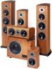 |


Resumen del manual
These features provide exceptional clarity, transparency, dynamics and power handling. The units are housed within vented aluminium chassis reducing stray magnetic flux to a minimum and increasing power handling. The tweeter - or treble driver - is a high-quality neodymium unit with a silk fabric dome integrating smoothly with the rest of the system. All drive units are fully magnetically shielded so that the speakers can be used in close proximity to a TV screen or monitor for AV applications. The Acoustic Energy AELITE Three loudspeaker uses quality OFC internal wiring, which enhances detail and transparency. Positioning The AELITE Threes are best heard with the tweeters at, or just below, ear height when the listener is seated. For serious listening the grilles are best removed. Rigid support is essential for the speaker to develop its full detail and dynamic performance. It is essential that the plinth supplied is fitted using the four screws provided. This is best acheived by standing the speaker on its top giving good access to the pre- drilled pilot holes. Once the plinth is attached then the supplied spikes (with lock nut on) should be threaded in to each corner. Carefully turn the speaker over so it is in its correct orientation and place in the desired position. Closeness to room boundaries has a major impact on the low frequency performance. The speakers should be kept away from corners (which will produce booming). The speakers can be positioned fairly close to a back or side wall but should not be the same distance off the ground as they are from the rear or side wall. For best stereo imaging the speakers should be as far apart as they are from the listening position. When the best position has been established then use the adjustable spikes to make sure the speaker is as stable as possible. Once achieved fix spikes in place using the locknuts Trust your own ears for the best listening position. Connection Check that your amplifier is switched off before installing your loudspeakers. Failure to do so may result in speaker or amplifier damage. The diagram illustrates one loudspeaker only. Conventional Normal passive wiring requires shorting links to be in place between the treble and mid/bass sections. The positive (ribbed) cable from the amplifier positive (or red) terminal should connect with the positive (red) terminal on the loudspeaker. Similarly the negative (smooth) cable should connect the amplifier negative terminal (black) to the negative terminal (black) on the loudspeaker. Bi-wiring Bi-wiring separates the bass and treble ground paths in the loudspeaker and offers sound quality advantages. An extra set of cables is required. Note that the shorting links are removed between the treble and mid/bass sections and should be stored for later use if conventional, passive driving is required. Two pairs of cables are connected to the amplifier terminals. One cable of each pair should connect to the treble section and one to the mid/bass section. The positive (ribbed) cables from the amplifier positive (or red) terminal should connect with the positive (red) terminals on the loudspeaker. Similarly the negative (smooth) cables in each pair should connect the amplifier negative terminal (black) to the negative terminals (black) on the loudspeaker. Bi-amping Bi-amping adds a second amplifier to the system. One power amplifier drives the treble section of both loudspeakers; a second drives the mid/bass sections. Note that the shorting links must be removed. Failure to do so will result in damaging the amplifiers. As regards the loudspeakers, wiring for bi-amping is achieved in much the same way as bi-wiring. Treble amplifier positive (red) terminals should be connected via the ribbed cable to the positive (red) HF terminal on the speaker. Similarly, treble amplifier negative is connected to the negative (black) HF terminal on the speaker. Repeat this process with the mid/bass amplifier and LF terminal pair. After wiring up Lower the volume to the minimum, switch on the amplifier, select the signal source and then raise the volume to the listening level required. AMPLIFIER LEFT SPEAKER RETAIN LINKS FOR FUTURE USE R L MAIN Specifications HF unit MF units LF units Crossover Power Handling Frequency response ±6dB Frequency response ±3dB Sensitivity Impedance Cabinet Terminals Weight (excl. packaging) Dimensions (WxHxD) Neodynium tweeter with high dispersion 25mm diaphragm. Ferro fluid cooled and damped. Magnetically shielded. Exclusively profiled aluminium front plate. Pure piston 110mm driver with a 32mm short-throw voice coil, Die-cast aluminium chassis, high power, shielded magnet system. Twin Pure piston 110 mm drivers with 32mm voice coils, Die-cast aluminium chassis, high power, long-throw magnet systems and alloy cones. Magnetically shielded. @ 3.3 kHz, 3rd order, high power. 175W max (undistorted program drive) 34Hz to 27kH 40Hz to 24kHz 89 dB/W/M 8 ohm Real wood veneered. 15 mm MDF wall. Twin...