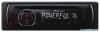
Manual de usuario Pioneer, modelo DEH-110E
Otros manuales para este modelo:
Resumen del manual
Use of unauthorized parts may cause malfunctions. Consult your dealer If Installation requires drilling of holes or other modifications to the vehicle. Do not Install this unit where : — It may Interfere with operation of the vehicle. — It may cause Injury to a passenger as a result of a sudden stop. The semiconductor laser will be damaged If It overheats. Install this unit awayfrom hot places such as near the heater outlet. Optimum performance Is obtained when the unit Is Installed at an angle of less than 60°. DEH-112E DEH-110E Installation Manual Manual de instalación Installationsanleitung Manuel d'installation Manuale d'installazione Installatiehandleiding Руководство по установке Printed in Thailand Imprimé en Thaïlande EW DIN front/rear mount This unit can be properly installed either from “Front” (conventional DIN front-mount) or “Rear” (DIN rear-mount installation, utilizing threaded screw holes at the sides of unit chassis). For details, refer to the following installation methods. DIN Front-mount Installation with the rubber bush 1 Insert the mounting sleeve into the dashboard. When installing in a shallow space, use a supplied mounting sleeve. If there is enough space behind the unit, use factory supplied mounting sleeve. <08H00000> 2 Secure the mounting sleeve by using a screwdriver to bend the metal tabs (90°) into place. 3 Install the unit. Dashboard Rubber bush DIN Rear-mount 1 Extend top and bottom of the trim ring outwards to remove the trim ring. (When reattaching the trim ring, point the side with a groove downwards and attach it.) Mounting sleeve Screw • It becomes easy to remove the trim ring if the front panel is released. Trim ring Removing the unit 1 Extend top and bottom of the trim ring outwards to remove the trim ring. (When reattaching the trim ring, point the side with a groove downwards and attach it.) Trim ring • It becomes easy to remove the trim ring it the front panel is released. 2 Insert the supplied extraction keys into both sides of the unit until they click into place. 3 Pull the unit out of the dashboard. 2 Determine the appropriate position where the holes on the bracket and the side of the unit match. 3 Tighten two screws on each side. Screw Mounting bracket Dashboard or console • Use either truss screws (5 mm x 8 mm) or flush surface screws (5 mm x 9 mm), depending on the shape of screw holes In the bracket. 0 C ) Fastening the front panel If you do not plan to detach the front panel, the front panel can be fastened with supplied screw. Screw a En (Instalación ~) ( Importante • Compruebe todas las conexiones y sistemas antes de la Instalación final. • No utilice piezas no autorizadas. El uso de piezas no autorizadas puede causarfallos de funcionamiento. • Consulte a su concesionario si para la Instalación es necesario taladrar orificios o hacer otras modificaciones al vehículo. • No Instale esta unidad en un lugardonde: — pueda Interferir con la conducción del vehículo. — pueda lesionar aun pasajero como consecuencia de un frenazo brusco. • El láser semiconductor se dañará si se sobrecalienta. Instale esta unidad alejada de zonas que alcancen altas temperaturas, como cerca de la salida del calefactor. • Se logra un rendimiento óptimo si la unidad se Instala en un ángulo Inferior a 60°. Montaje delantero/ posterior DIN Esta unidad se puede Instalar adecuadamente ya sea de manera “delantera” (montaje delantero convencional DIN) o “posterior” (Instalación de montaje posterior DIN, utilizando agujeros roscados para tornillos en los latera-es del bastidor de la unidad). Para obtener detalles, consulte los siguientes métodos de instalación. Montaje delantero DIN Instalación en la arandela de goma 1 Inserte el manguito de montaje en el salpicadero. Si realiza la instalación en un espacio poco profundo, utilice un manguito de montaje suministrado. Si hay suficiente espacio detrás de a unidad, utilice un manguito de montaje suministrado de fábrica. 2 Fije el manguito de montaje utilizando un destornillador para doblar las pestañas metálicas (90°) y colocarlas en su lugar. 3 Instale la unidad. Sal picadero Arandela de goma Retirada de la unidad 1 Extienda hacia afuera la parte superior e inferior del aro de guarnición para retirarlo. (Al volver a colocar el anillo de guarnición, oriente el lado que tiene una ranura hacia abajo y colóquelo.) • Resulta más fácil retirar el anillo de guarnición si se suelta la carátula. Es (Instalación C ) 2 Inserte en ambos lados de la unidad las llaves de extracción provistas hasta que se escuche un ligero chasquido. 3 Extraiga la unidad del salpicadero. Montaje trasero DIN 1 Extienda hacia afuera la parte superior e inferior del aro de guarnición para retirarlo. (Al volver a colocar el anillo de guarnición, oriente el lado que tiene una ranura hacia abajo y colóquelo.) • Resulta más fácil retirar el anillo de guarnición si se suelta la carátula. 3 ...
Otros modelos de este manual:
Unidad - DEH-112E (482.32 kb)


 )
)