


Votos - 2, Puntuación media: 3.5
(


 )
)
|
Fotos y especificaciones Sony HVL-F58AM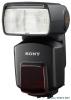 |


Resumen del manual
73 Custom setting ....................................................................................... 74 Additional Information Additional Information 1 Maintenance ........................................................................................... 83 Specifications ........................................................................................ 84 Before use Before use This flash unit is not dust-proof, splash-proof or waterproof. Do not place this flash unit in the following locations Regardless of whether this flash unit is in use or in storage, do not place it in any of the following locations. Doing so may lead to a malfunction. • Placing this flash unit in locations subject to direct sunlight such as on dashboards or near a heater may cause this unit to deform or malfunction. • Locations with excessive vibration • Locations with strong electromagnetism • Locations with excessive sand In locations such as the seashore and other sandy areas or where dust clouds occur, protect the unit from sand and dust. This may lead to a malfunction. Features Features The HVL-F58AM is a functional, clip-on flash that provides a large flash output with a guide number of 58 (105 mm position, ISO 100 · m). Can be used with compatible lenses to enable ADI (Advanced Distance Integration) flash metering, which is not affected by the reflection rate of the background or subject. Enables wireless High-speed Sync. Quick shift bounce function enables you to set the upper or side position easily during bounce flash photography. Built-in bounce sheet enables you to create a highlight in the subject’s eyes. Equipped with a wide, easy-to-see LCD panel. This flash unit supports flash coverage to a focal length of 16 mm by using a built-in wide panel when the flash is triggered. Corrects the white balance automatically using the color temperature information.* Adjusts the optimum flash coverage according to the image sensor size of the camera.* , , , , , , , , page 84 page 43 page 47 page 36 page 36 page 13 page 34 page 28 page 32 * When Sony digital single-lens reflex camera (other than the DSLR-A100) is used. Name of parts Name of parts A Built-in wide panel (page 34) E Mounting foot (page 18) B Flashtube F Terminal cap (page 69, 71) C Wireless control signal receiver G Bounce sheet (page 36) (page 54) D AF illuminator (page 72) Remove the protective sheet from the front of the AF illuminator before use. * H Bounce indicator (upper angle) K Bounce indicator (side angle) (page 36) (page 36) I LCD panel (page 13) L Mounting-foot release button J Control panel (page 12) (page 19) M Battery-chamber door (page 15) N Mini-stand (page 57) * Tripod mount Control panel Control panel A TTL/M (MANUAL/MULTI) E POWER switch (page 20) button (page 44, 48, 61, 66, 73) F LCD illuminator button B MODE button (page 22) (page 24) C TEST button (page 31) G ZOOM button (page 32) The status while the lamp is lit Amber: Flash ready Green: Proper exposure D Fn (function)/direction buttons (page 44, 48, 61, 64, 66, 74) LCD panel LCD panel A Zoom indicator (page 32) B Flash mode indicator (page 22, 61, 64, 66) C Flash-OFF indicator (page 22) D Power-level indicator (page 43, 48) E Zoom/Multiple-flash repetition display (page 32, 48) F mm indicator (page 32) G TIMES indicator (page 48) H Bounce indicator (page 36) I Custom indicator (page 74) J High-speed-sync indicator (page 47) K Wide-panel indicator (page 34) L Low-battery indicator (page 16) M OVERHEAT indicator (page 17) N STANDBY indicator (page 21) O Wireless channel indicator (page 54) P Wireless controller indicator (page 54) Q Wireless controller/remote indicator (page 54) R Flash-range/Multiple-flash frequency/flash-ratio display (page 27, 48, 66) S Ratio-flash indicator (page 66) T Operating indicator (page 78) U Flash-range-warning (near side) indicator (page 27, 43) V TTL indicator (page 43) W Manual-flash indicator (page 43) X Multiple-flash indicator (page 48) Y Flash-range-warning (far side) indicator (page 27, 43) Z ft/m indicator (page 27, 43) wj Hz indicator (page 48) Inserting batteries Inserting batteries • Four AA-size alkaline batteries* • Four AA-size rechargeable nickel-metal hydride (Ni-MH) batteries* * Batteries are not supplied. Always ensure that rechargeable nickel-metal hydride batteries are charged in the specified charger unit. 1 Open the battery-chamber door as shown. 2 Insert the batteries in the battery chamber as in the diagram. 3 Close the battery-chamber door. • Follow the reverse procedure when opening the battery-chamber door. Preparations 15 Checking Batteries Checking Batteries indicator on the data panel blinks when the batteries are low. blinking Changing the batteries is recommended. The flash unit can still be used when the TEST button lights up in amber. Only blinking Flash cannot be used. Insert new batteries. • If nothing appears on the LCD panel when the POWER switch is set to ON, check the orientation of the batteries. OVERHEAT indicato...