


Votos - 3, Puntuación media: 4
(

 )
)
|
Fotos y especificaciones Humminbird ICE 45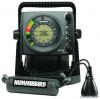 |


Resumen del manual
1. Connect the transducer to the control head. The slots are keyed to prevent reverse installation, so be careful not to force the connector into the holder. 2. Drop the transducer into the ice hole. If the transducer is working properly, you will see the bottom displayed on the Flasher Dial as a red line. WARNING: Before walking onto the ice, make sure that conditions are safe. 2. Assembling the Transducer and Float In this procedure you will assemble the transducer and float. Float Attaching the Float to the Support Cable Signal Cable Support Cable Cable Support Clip Transducer 1. Thread the support cable through the support clip and then clip onto the transducer. 2. Attach your transducer float to the support cable by sliding the support cable through the slit in the float. NOTE: Attaching the float is optional. You can also use the storage posts to hold the support cable in position. Threading Support Cable through Support Clip 3. Position the float so that the transducer will be submerged in the water, just below the ice. IceLayerFloatTransducer NOTE: The transducer must be submerged in water for reliable transducer detection. The bottom of the transducer should be even with the bottom of the ice or hang slightly below the bottom of the ice. AttachingtheCableClampsSupportCableSupportCable 4. Cable Clamp (acts as a stop for the support cable, sets depth of transducer in ice hole - see Procedure 2, step 4) Signal Cable Cable Clamp (provides cable management for signal cable -see Procedure 2, step 5) 5. Signal Cable Once you know where you want to position your float, place one of the cable clamps onto the support cable, above the float. Use the inside, smaller cable hole for the support cable so that the float will not move, and so that the transducer will maintain its position under the ice. Make sure that the support cable is taut, so that the transducer hangs straight down (see illustration). Cable Clamp Signal Cable Hole Support Cable Hole If you would like to keep the support and signal cables together above the float stop, attach a cable management clamp (included) to the support cable (using the inner, smaller hole) and the signal cable (using the outer, larger hole). Make sure that the signal cable has some slack so that it is not bearing the weight of the transducer. 3. Connecting the Transducer Cable This section covers how to connect your transducer cable to your control head. NOTE: If you have an ICE 55 Flasher, remove the control head and base from the portable bag first. 1. Insert the transducer cable into the appropriate terminal slot on the rear of the control head. NOTE: The slots are keyed to prevent reversed installation, so be careful not to force the connector onto the holder. 2. Route the transducer signal cable beneath the control head and secure to cable clips on the base. ConnectingtotheICEFlasherSeries™Fishfinder TransducerSignalCableCableClips 3. Reinstall assembled control head, base, and transducer into portable bag (ICE 55 only). 4. Storing the Transducer When you are done fishing, store the transducer using the following guidelines: 1. Wipe the cable dry. 2. Tuck the float under the control head, and wrap the cable around the storage posts. Store the transducer in the transducer well. NOTE: You do not have to detach the transducer cable from the control head to store the transducer. CAUTION: Although the transducer signal cable is designed to be flexible in cold temperatures, you must store your cable correctly to avoid stressing it. Make sure it is coiled smoothly, with no kinks, and that it is clear of the zippers on the portable bag. Storing the Transducer CableWrappedAroundStoragePostsFloatTuckedUnderControlHead Transducer Well TEST AND FINISH THE INSTALLATION Once you have assembled both the ICE Flasher Series™ control head and the Ice Fishing transducer, and have routed all the cables, you should perform a final test. Testing should be performed with the transducer in the water. 1. After connecting the transducer to the control head, and confirming that the power cable is connected to the battery, drop the transducer into the ice hole to confirm proper operation. WARNING: Before walking onto the ice, make sure that conditions are safe. 2. Turn the Power/Range dial to A (Auto) or x1 to power-on the control head. NOTE: If the unit does not power up, make sure that the connector is fully seated in the back of the control head, the power cable is connected to the battery, and the battery is charged. 3. If all connections are correct and power is available, the Humminbird® control head will enter Normal operation, and you should see the bottom on the control head display. 4. If the bottom is visible on-screen with a digital depth readout, the unit is working properly (ICE 35 will only display the bottom on the Flasher Dial). NOTE: The transducer must be submerged in water for reliable transducer detection. The bottom of the transducer should be even with the bottom of the ...
Otros modelos de este manual:equipamiento barco - ICE 35 (1.19 mb)
equipamiento barco - ICE 55 (1.19 mb)