


Votos - 4, Puntuación media: 4
(

 )
)
|
Fotos y especificaciones Sony MDS-PC3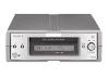 |


Resumen del manual
= 780 nm) Emission duration: continuous Laser output Less than 44.6 .W* * This output is the value measured at a distance of 200 mm from the objective lens surface on the Optical Pick-up Block with 7 mm aperture. Laser diode Material: GaAlAs Revolutions (CLV) 400 rpm to 900 rpm Error correction Advanced Cross Interleave Reed Solomon Code (ACIRC) Sampling frequency 44.1 kHz Coding Adaptive Transform Acoustic Coding (ATRAC) Modulation system EFM (Eight-to-Fourteen Modulation) Number of channels 2 stereo channels Frequency response 5 to 20,000 Hz ±0.5 dB Signal-to-noise ratio Over 94 dB during playback Wow and flutter Below measurable limit Inputs LINE (ANALOG) IN Jack type: stereo-mini Impedance: 47 kilohms Rated input: 500 mVrms Minimum input: 125 mVrms DIGITAL (OPTICAL) IN Connector type: square optical Impedance: 660 nm (optical wave length) Outputs LINE (ANALOG) OUT (VARIABLE) Jack type: stereo-mini Rated output: 1 Vrms (at 50 kilohms) Load impedance: Over 10 kilohms DIGITAL (OPTICAL) OUT Connector type: square optical Rated output: –18 dBm Impedance: 660 nm (optical wave length) PHONES Jack type: stereo-mini Rated output: 5 mW Load impedance: 32 ohms General Where purchased Power requirements* U.S.A. and Canada 120 V AC, 60 Hz Other countries 220 – 230 V AC, 50/60 Hz * Using an AC power adaptor (supplied) Power consumption 7 W Dimensions (approx.) 152 . 52 . 255 mm (6 . 2 1/8 . 10 1/8 inches) (w/h/d) incl. projecting parts and controls Mass (approx.) 1.0 kg (2 lb 4 oz) Supplied accessories • AC power adaptor (1) • Audio connecting cord (stereo mini-plug . 1 y stereo mini-plug . 1) (1) • Optical cable (1) • Remote commander (remote) RM-D52M (1) • PC connecting kit PCLK-MN10* (1) * Required for operation by personal computer. For details, refer to the operating instructions supplied with the PCLK-MN10. MINIDISC DECK t“[TOC *Note: As this unit has only a few buttons, one button is assigned with several functions in the test mode.” Press the z button, AMS knob to switch the functions. • Each time the z button is pressed, the display switches in the follwing order, “PGM” t “blank” t “PGM” t –. • Rotate the AMS knob and the display switches in the following order, “blank” t “TOC” t “EDIT” t “TOC EDIT” t “[ ]” ]” t “[ EDIT]” t “[TOC EDIT]” t “blank” t – –. For simplicity, operations of z button will not be discribed here. Example) x/Z “PGM” x/Z : Lights-out “PGM” and press the x/Z button. : Display “PGM” and press the x/Z button. The functions of each button change with the display. Bottons and Corresponding Functions Buttons “PGM” displayed “PGM” Lights-out LCD displayed Nothing displayed TOC EDIT TOC EDIT TOC EDIT TOC EDIT @/1 @/1 ENTER (YES) REPEAT PLAY CLEAR FF PLAY MODE DISPLAY — MENU x/Z EJECT (EDIT)/ STOP REC — FR SCROLL TIME — NO SELF-DIAGNOSIS FUNCTION The self-diagnosis function consists of error codes for customers which are displayed automatically when errors occur, and error codes which show the error history in the test mode during servicing. For details on how to view error codes for the customer, refer to the following box in the instruction manual. For details on how to check error codes during servicing, refer to the following “Procedure for using the Self- Diagnosis Function (Error History Display Mode)”. Self-Diagnosis Function The deck’s self-diagnosis function automatically checks the condition of the MD deck when an error occurs, then issues a three-digit code and an error message on the display. If the code and message alternate, find them in the following table and perform the indicated countermeasure. Should the problem persist, consult your nearest Sony dealer. Three-digit code/Message Cause/Remedy C14/Toc Error The deck could not read the TOC on the MD properly. C11/Protected The inserted MD is record-protected. , Insert another disc. , Take out the MD and close the record-protect slot (page 13). , If possible, erase all the tracks on the MD (page 29). C12/Cannot Copy An attempt was made to play a disc that is not compatible with this deck C41/Cannot Copy The digitally dubbed material cannot be recorded digitally (page 11). (MD data disc, etc.). C71/Din Unlock The sporadic appearance of this message is caused by the digital signal being , Replace the disc. recorded. This will not affect the recording. C13/Rec Error The recording was not made properly. While recording from a digital component connected through the DIGITAL , Set the deck in a stable surface, and repeat the recording procedure. (OPTICAL) IN connector, the digital connecting cable was unplugged or the The inserted MD is dirty (with smudges, fingerprints, etc.), scratched, or digital component turned off. substandard in quality. , Connect the cable or turn the digital component back on. , Replace the disc and repeat the recording procedure. E0001/MEMORY NG There is an error in the internal data that the deck needs in order to operate. C13/Read Error The deck could not read the TOC on the MD properly. , Consult your neares...