


Votos - 3, Puntuación media: 3.7
(

 )
)
|
Fotos y especificaciones Makita 3612C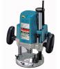 |


Resumen del manual
Minute depth adjustments can be obtained by turning the stopper pole (1.5 mm or about 1/16” per turn). Now, your predetermined depth of cut can be obtained by loosening the lock lever and then lowering the tool body until the stopper pole makes contact with the adjusting hex bolt. By turning the knob, the upper limit of the tool body can be adjusted. When the tip of the bit is retracted more than required in relation to the base plate surface, turn the knob to lower the upper limit. CAUTION: • Since excessive cutting may cause overload of the motor or difficulty in controlling the tool, the depth of cut should not be more than 20 mm (13/16”) at a pass when cutting grooves. When you wish to cut grooves more than 20 mm (13/16”) deep, make several passes with progressively deeper bit settings. • Do not lower the knob too low. The bit will protrude dangerously. 1 2 34 1 2 34 Stopper pole 2. Hex bolt 3. Hex nut 4. Stopper block 003657 Stopper block The stopper block has three adjusting hex bolts which raise or lower 0.8 mm (1/32”) per turn. You can easily obtain three different depths of cut using these adjusting hex bolts without readjusting the stopper pole. Adjust the lowest hex bolt to obtain the deepest depth of cut, following the method of “Adjusting depth of cut”. Adjust the two remaining hex bolts to obtain shallower depths of cut. The differences in height of these hex bolts are equal to the differences in depths of cut. To adjust the hex bolts, first loosen the hex nuts on the hex bolts with the wrench and then turn the hex bolts. After obtaining the desired position, tighten the hex nuts while holding the hex bolts in that desired position. The stopper block is also convenient for making three passes with progressively deeper bit settings when cutting deep grooves. 1 1. Switch lever 003660 Switch action CAUTION: • Before plugging in the tool, always check to see that the tool is switched off. • Switch can be locked in “ON” position for ease of operator comfort during extended use. Apply caution when locking tool in “ON” position and maintain firm grasp on tool. • Make sure that the shaft lock is released before the switch is turned on. • Hold the tool firmly when turning off the tool, to overcome the reaction. To start the tool, move the switch lever to the I (ON) position. To stop the tool, move the switch lever to the O (OFF) position. Electric brake This tool is equipped with an electric brake. If the tool consistently fails to quickly stop after switch lever moving to the O (OFF) position, have tool serviced at a Makita service center. 1 1 Speed adjusting dial Speed adjusting dial 003802 For model 3612C only The tool speed can be changed by turning the speed adjusting dial to a given number setting from 1 to 5. Higher speed is obtained when the dial is turned in the direction of number 5. And lower speed is obtained when it is turned in the direction of number 1. This allows the ideal speed to be selected for optimum material processing, i.e. the speed can be correctly adjusted to suit the material and bit diameter. Refer to the table for the relationship between the number settings on the dial and the approximate tool speed. CAUTION: • If the tool is operated continuously at low speeds for a long time, the motor will get overloaded, resulting in tool malfunction. • The speed adjusting dial can be turned only as far as 5 and back to 1. Do not force it past 5 or 1, or the speed adjusting function may no longer work. CAUTION: • Always be sure that the tool is switched off and unplugged before carrying out any work on the tool. 003670 Installing or removing the bit CAUTION: • Install the bit securely. Always use only the wrench provided with the tool. A loose or overtightened bit can be dangerous. • Do not tighten the collet nut without inserting a bit or install small shank bits without using a collet sleeve. Either can lead to breakage of the collet cone. Insert the bit all the way into the collet cone. Press the shaft lock to keep the shaft stationary and use the wrench to tighten the collet nut securely. When using router bits with smaller shank diameter, first insert the appropriate collet sleeve into the collet cone, then install the bit as described above. To remove the bit, follow the installation procedure in reverse. Number RPM 1 9,000 2 12,000 3 15,000 4 19,000 5 23,000 ASSEMBLY 1 2 3 1. Wrench 2. Shaft lock 3. Lock lever OPERATION 1 1. Chip deflector 003803 CAUTION: • Before operation, always make sure that the tool body automatically rises to the upper limit and the bit does not protrude from the tool base when the lock lever is loosened. • Before operation, always make sure that the chip deflector is installed properly. Set the tool base on the workpiece to be cut without the bit making any contact. Then turn the tool on and wait until the bit attains full speed. Lower the tool body and move the tool forward over the workpiece surface, keeping the tool base flush and advancing smoothly ...
Otros modelos de este manual:Tratamiento de la madera de placas - 3612 (179.24 kb)