


Votos - 3, Puntuación media: 3
(

 )
)
|
Fotos y especificaciones Star Trac E-TBTi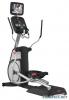 |


Resumen del manual
• Connect the DC power from the PVS display neck to the other DC connector on the front display center console board. • Connect the Remote cable from the PVS display neck to the Remote connector on the front display center console board. • Connect the RCA cable from the PVS display neck to the RCA connector on the front display center console board. • Connect the Ground cable from the front display Heart Rate board to one of the terminals on the display mount. • Connect the Ground cable from the front display Center Console to one of the terminals on the display mount. 5 2 4 7 6 6 3 1 Tie Wrap STEP 19 Feed the Head Phone Jack cable from the PVS display neck through the hole in the front display plastics where the blank cover was removed earlier. STEP 20 Now that all the cables are in their places, and confined to the post on the display mount. Place the display front plastic onto the back. Make sure the bottom of the display front is under the 2 tabs on the display mount. Press the front display against the round tube and rotate it to the back. Be careful not to pinch any wires. STEP 21 Using a #2 Phillips screwdriver, secure the front display to the back with the (8) screws you previously removed and saved. STEP 22 Take the Entertainment Head Phone Jack from the PVS kit and attach it to the cable that is hanging out of the front of the display. Make sure the connector is seated all the way into the jack. Now slide the jack into the front of the display. Using a #2 Phillips screwdriver, fasten the head phone jack into the front display with the screw that was saved from the earlier step. 16 STAR TRAC PERSONAL VIEWING SCREEN OWNER’S GUIDE 2 1 Screws Screws Screw STEP 23 Now with the Personal Viewing Screen installed on your Star Trac equipment, it is time to connect your entertainment cable and power to the unit Look at the bottom of the neck, next to the floor. Connect your in-house Entertainment cable to the RF input. Take the power supply from the PVS kit and plug the small barrel connector to the DC input. Now take the appropriate Power Adapter Cable from the kit and plug it into the power supply and the electrical receptacle. Only use the power supply that was provided in your Personal Viewing Screen Kit. Using the wrong supply may damage your PVS. This completes the installation of the Personal Viewing Screen. Now it is time to set it up. Turn to the appropriate section for your Personal Viewing Screen. STAR TRAC PERSONAL VIEWING SCREEN OWNER’S GUIDE To install on the E-TR, follow these steps: STEP 1 Using a #2 Phillips screwdriver, remove the (8) screws from the upper back of the display. Place the cover somewhere safe to keep it from being damaged. Next, remove the (6) screws from the lower back of the display. Place the cover with the other one. Retain all the screws for later use. STEP 2 Now remove the upper cap cover that has the STAR TRAC logo on it. This cap is held in by the upper back cover. You will no longer need this cap cover and, if desired, you can store it away for any possible future use. STEP 3 Using a #2 Phillips screwdriver, remove the screw that holds in the Blank Head Phone Jack Cap at the lower front of the display. Retain the screw. You will no longer need the cap and, if desired, you can store it away for any possible future use. Now take the Entertainment Head Phone Jack from the PVS hardware kit. Use the previously retained screw to reinstall the Headphone Jack. Tighten snugly. 18 STAR TRAC PERSONAL VIEWING SCREEN OWNER’S GUIDE Cap Screw Blank Cap New Head Phone Jack Screws Screws Screws Screws STEP 4 Detach the Center Console Ribbon Cable from the display board by gently pulling on the ribbon connector. Using a #2 Phillips screwdriver to remove the (4) screws that hold the center console in place. Retain the screws for later use. Remove the center console. You will no longer need this center console and, if desired, you can store it away for any possible future use. STEP 5 Take the Personal Viewing Screen from the PVS kit. Next, take the (3) M8 Buttonhead screws, the M8 Hex nut with washer, and the 5mm Hex key from the PVS hardware tool kit. STEP 6 Mount the Personal Viewing Screen on the Treadmill. Using the 5mm hex key, screw in the (2) M8 Buttonheads at the base of the PVS first (do not tighten yet). Using the 5mm hex key put one of the M8 Buttonhead screws into the hole on the PVS neck, then put the hex nut with washer on the back side (do not tighten). STEP 7 Adjust the display cap up or down to align with the holes on the display front. Once the cap is aligned, tighten the buttonhead screws with the 5mm hex key. STAR TRAC PERSONAL VIEWING SCREEN OWNER’S GUIDE 19 Ribbon Screws Screws Screws Align Align STEP 8 Now that the PVS is mounted to the Treadmill, you need to route the wires to their proper places. Take the coax cable and feed it all the way down the treadmill neck. Feed the DC power cable from the treadmill neck through the center console hole. Next take the Hea...
Otros modelos de este manual:Formadores - E-RBi (4.95 mb)
Formadores - E-STi (4.95 mb)
Formadores - E-TRi (4.95 mb)
Formadores - E-UBi (4.95 mb)