


Votos - 2, Puntuación media: 4.5
(

 )
)
|
Fotos y especificaciones Furuno LS-6100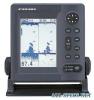 |


Resumen del manual
Otherwise the time required for complete “saturation” ill be lengthened and performance will be reduced. DO NOT paint the transducer. Performance will be affected. 28 4.4 Inside-hull Transducer The thru-hull mount transducer (520-5PSD, 520-5MSD) may also be installed inside the hull, following the procedure below. Necessary tools You will need the following tools: • Sandpaper (#100) • Silicone sealant • Silicone grease Remarks on installation • Turn off the engine and anchor the boat while installing the equipment. • Install the transducer in the engine room. Choosing the mounting location • Keep the following points in mind when choosing a mounting location: • The mounting location should be where the hull is of single-hull thickness and is void of air or flotation materials other than solid fiberglass between the transducer face and the water. • Do not place the transducer over hull struts or ribs which run under the hull. • Avoid a location where the rising angle of the hull exceeds 15°, to minimize the effect of the boat’s rolling. • You will finalize the mounting location through some trial and error. The procedure for this is shown later. 1/2 Centerline 50 cm 50 cm 15 cm 15 cm 1/3 Transducer mounting location Inside-hull transducer mounting location Attaching the transducer 1. Clean the transducer face to remove any foreign material. Lightly roughen the transducer face with #100 sandpaper. Also, roughen the inside of the hull where the transducer is to be mounted. 2. Warm the silicone sealant to 40°C before usage to soften it. Coat the transducer face and mounting location with silicone sealant. Transducer Silicone Sealant Coating transducer face with silicone sealant 3. Press the transducer firmly down on the hull and gently twist it back and forth to remove any air which may be trapped in the silicone sealant. Checking the installation 1. Connect the battery to the display unit. 2. Turn on the display unit. 3. Press the [MODE] key to choose SINGLE FREQ. 4. Choose 50 kHz or 200 kHz, and then press the [MENU/ESC] key to close the mode menu. 5. Press the [PROG] key to show the pop-up window for automatic/manual selection. 6. Press ^to choose Manual. 7. Press the [MENU/ESC] key.. 8. Press the [GAIN] key to set the gain to “5” and then press the [MENU/ESC] key. 9. Press the [RANGE] key to set the range to 10 meters (feet) and then press the [MENU/ESC] key. 29 10.If the bottom is displayed in dark gray and the depth indication appears, the mounting location is suitable. Go to “Final preparation.” 11. If the bottom is not displayed in dark gray tone, the mounting location may be unsuitable. Do the following: a) Press the [POWER/BRILL] key to turn off the power. b) Gently dismount the transducer with a piece of wood. c) Reattach the transducer elsewhere as shown in “Attaching the transducer.” d) Check the installation again. Final preparation Support the transducer with a piece of wood to keep it in place while it is drying. Let the transducer dry 24-72 hours. 4.5 Optional Triducer 525ST-MSD The optional triducer 525ST-MSD is designed for thru-hull mounting. For how to install this transducer see paragraph 4.2. .79 mm 133 mm 2.00"-12 UN threads 7 mm .51 mm 27 mm 140 mm Triducer 525ST-MSD 525ST-PWD The Transom Mount Transducer or TRIDUCER® Multisensor with Integral Release Bracket 525ST-PWD is manufactured by AIRMAR Co. These instructions are included with the sensor. Pre-test for speed and temperature Connect the sensor to the instrument and spin the paddlewheel. Check for a speed reading and the approximate air temperature. If there is no reading, return the sensor to your place of purchase. Tools and materials needed Scissors Masking tape Safety goggles Dust mask Electric drill Drill bit for: Bracket holes: 4mm, #23, or 9/64” Fiberglass hull: chamfer bit (preferred), 6mm, or 1/4” Transom hole: 19mm or 3/4” (optional) Cable clamp holes: 3mm or 1/8” Screwdrivers Straight edge Marine sealant Pencil Zip-ties Water-based antifouling paint (mandatory in salt water). Mounting location To ensure the best performance, the sensor must be submerged in aeration-free and turbulence-free water. Mount the sensor close to the centerline of the boat. On slower heavier displacement hulls, positioning it farther from the centerline is acceptable. Allow adequate space above the bracket for it to release and rotate the sensor upward. 30 Height without speed sensor 191mm (7-1/2") Height with speed sensor 213mm (8-1/2") Height Height required at mounting location Note 1: Do not mount the sensor in an area of turbulence or bubbles: near water intake or discharge openings; behind strakes, struts, fittings, or hull irregularities; behind eroding paint (an indication of turbulence). Note 2: Avoid mounting the sensor where the boat may be supported during trailering, launching, hauling, and storage. Note 3: For single drive boat, mount on the starboard side at least 75 mm (3”) beyond the swing radius of the propeller. 75 mm(3") swin...